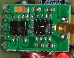
This is guess work but it seems right (to me): The W8681 uses a humidity to frequency circuit based on the sample application given on page 3 of the HS1101LF datasheet.
The two resistors at the bottom are R22 ("514"=510k ohms) and R4 ("513" = 51 k ohms) in the sample circuit. The calibration potentometer RV1 has been omitted - the units are probably calibrated in software (which I don't know how to change).
The sonsor's capacitance increases with humidity. The 555's output frequency decreases with increasing humidity.
I don't want to mess around with the surface mounted components, so I'm going to try some resistors across the sensor to find a value that helps, and if that works fit a potentometer and resistor in series across the sensor.
Subscribe to:
Post Comments (Atom)
2 comments:
what about your modifications? does the humidity sensor work correct now?
Hello Blogers!
I am asking for help, which resonator is placed on the board of the external transmitter between the RJ11 WIND REIN sockets and the battery contacts. It looks like a DCF just smaller, my legs have gone out.
Greetings, Marek
Post a Comment